


Properties of GRC
Acoustic performance
Well designed GRC can be effectively used as sound attenuating barriers alongside motorways and railways lines etc. For example a 10mm thick GRC panel will provide 20kg of mass per square meter which when combined with relief patterns and perforations designed to diffract sound the GRC panel will provide excellent sound / acoustic barriers.
Permeability, water absorption and apparent porosity
Well compacted GRC has inherently low water permeability and can be used as for drains, culverts, pits and water tanks.
Fire resistance
The basic constituents of GRC are inorganic and non-combustible. The fire performance classification according to standard test procedure is “A1”.
Toughness and impact resistance
GRC is inherently tougher and more impact resistant than standard concrete and many other fibre reinforced composites.
Recycling of GRC
GRC products are suitable for recycling in a similar way to standard concrete and in fact due to the relative high percentage of cement can contribute to the development of additional strength in concrete made from recycled aggregates.
What is GRC?
Constituent materials
Glass Fibre reinforced concrete (GRC) is a composite material made up of various constituent materials including; Binders (cement, pozzolans), Aggregates (silica sands), Fibre (Alkali resistant glass fibre), Admixtures (e.g. plasticisers, polymers, titanium dioxide, oxides etc) and water.
production
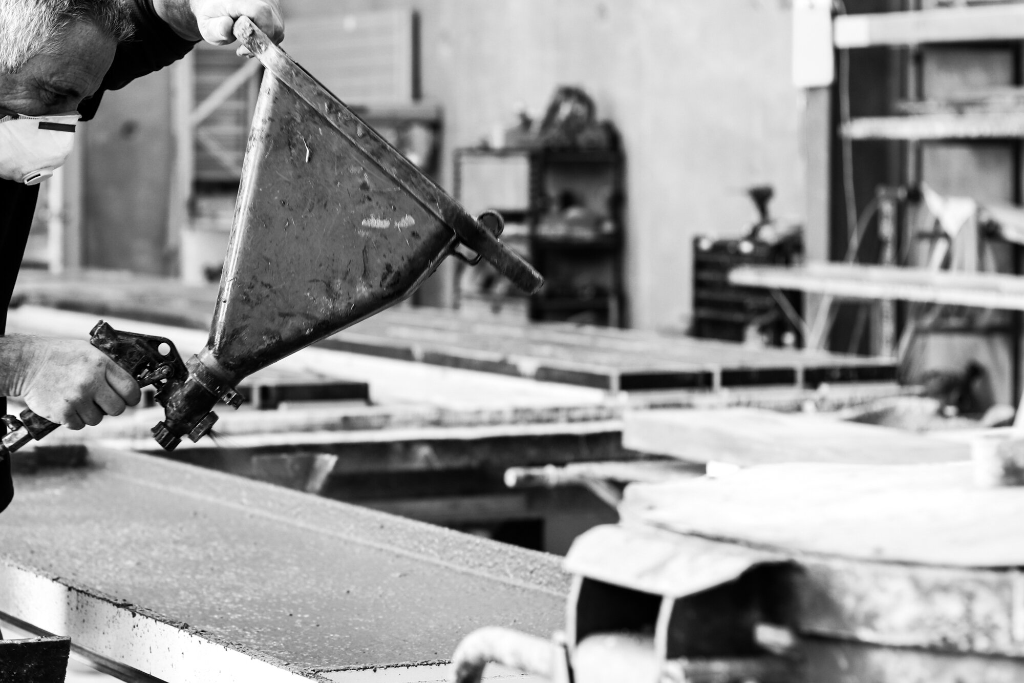
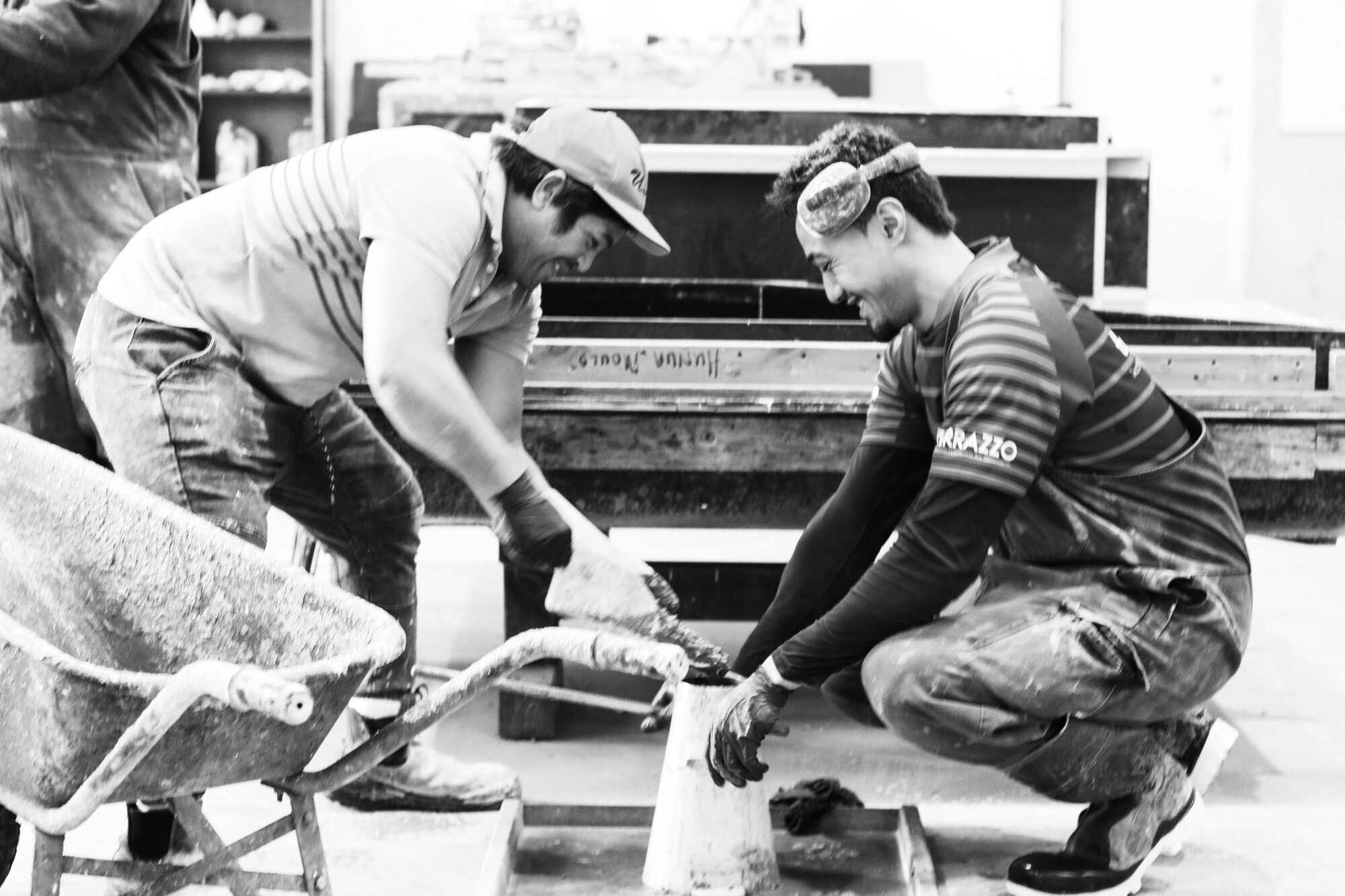
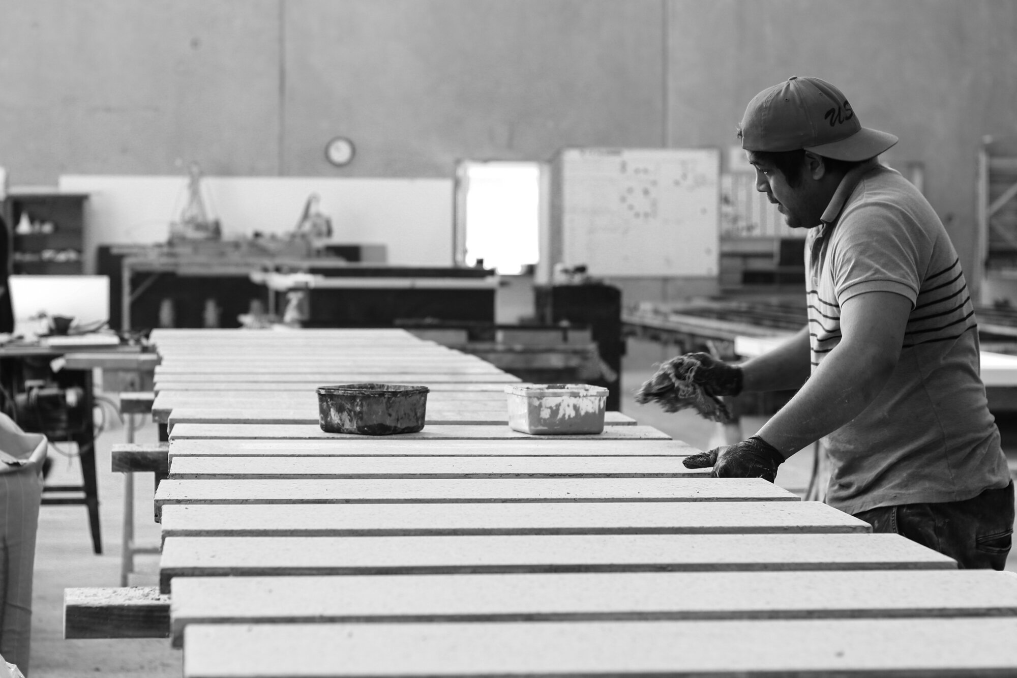
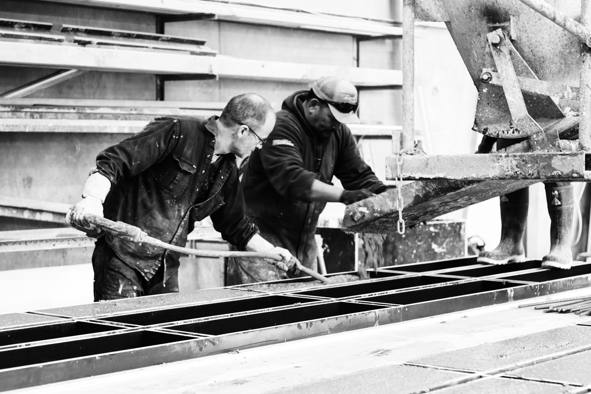
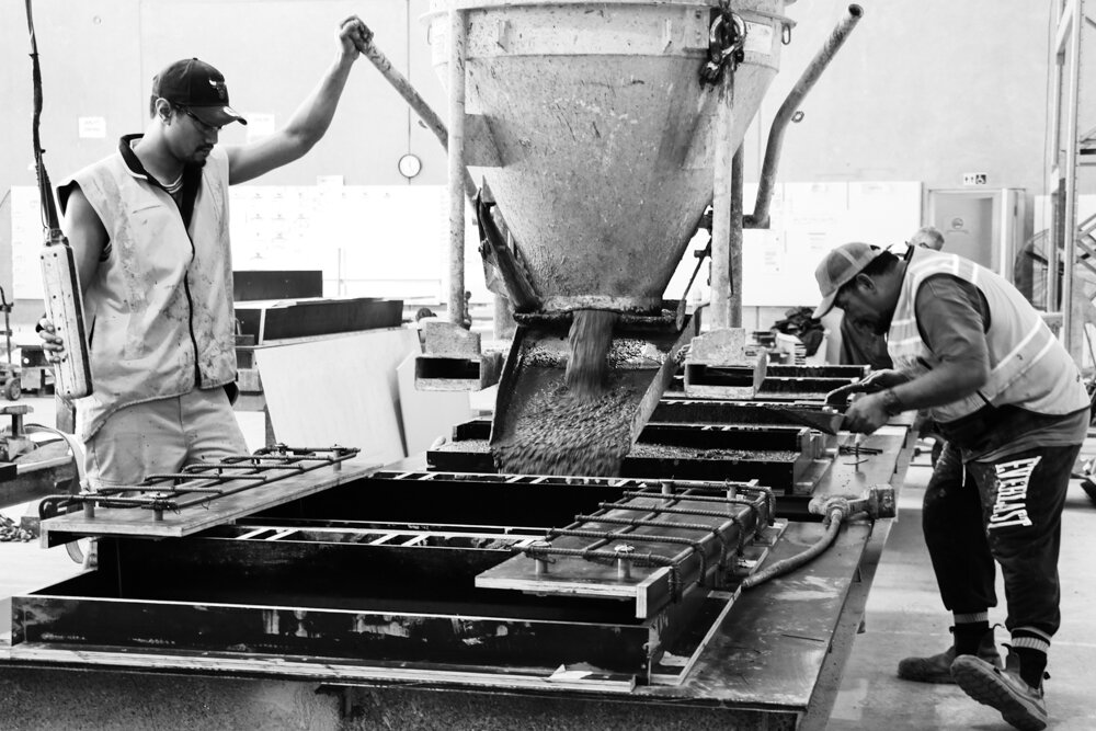
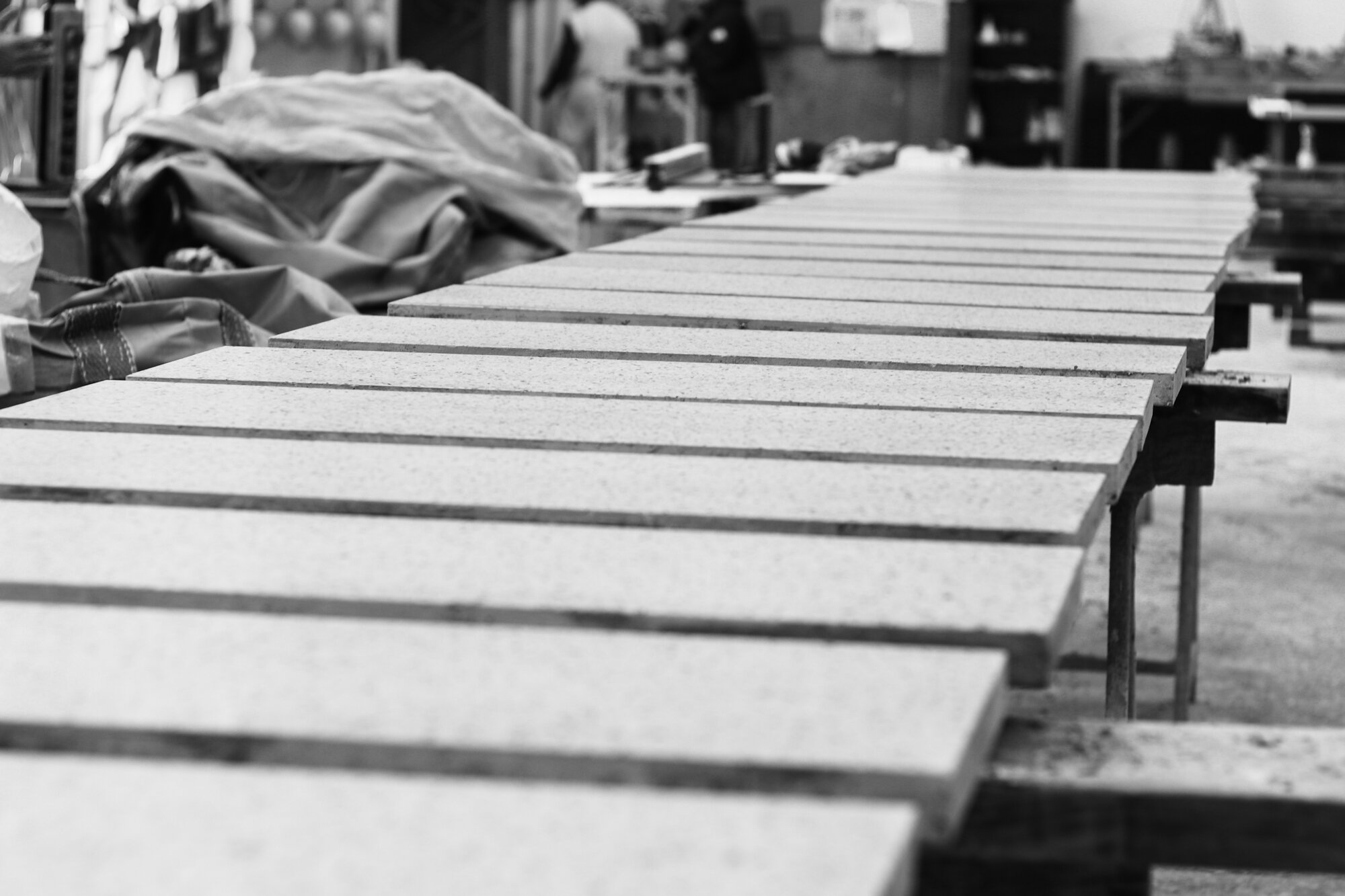
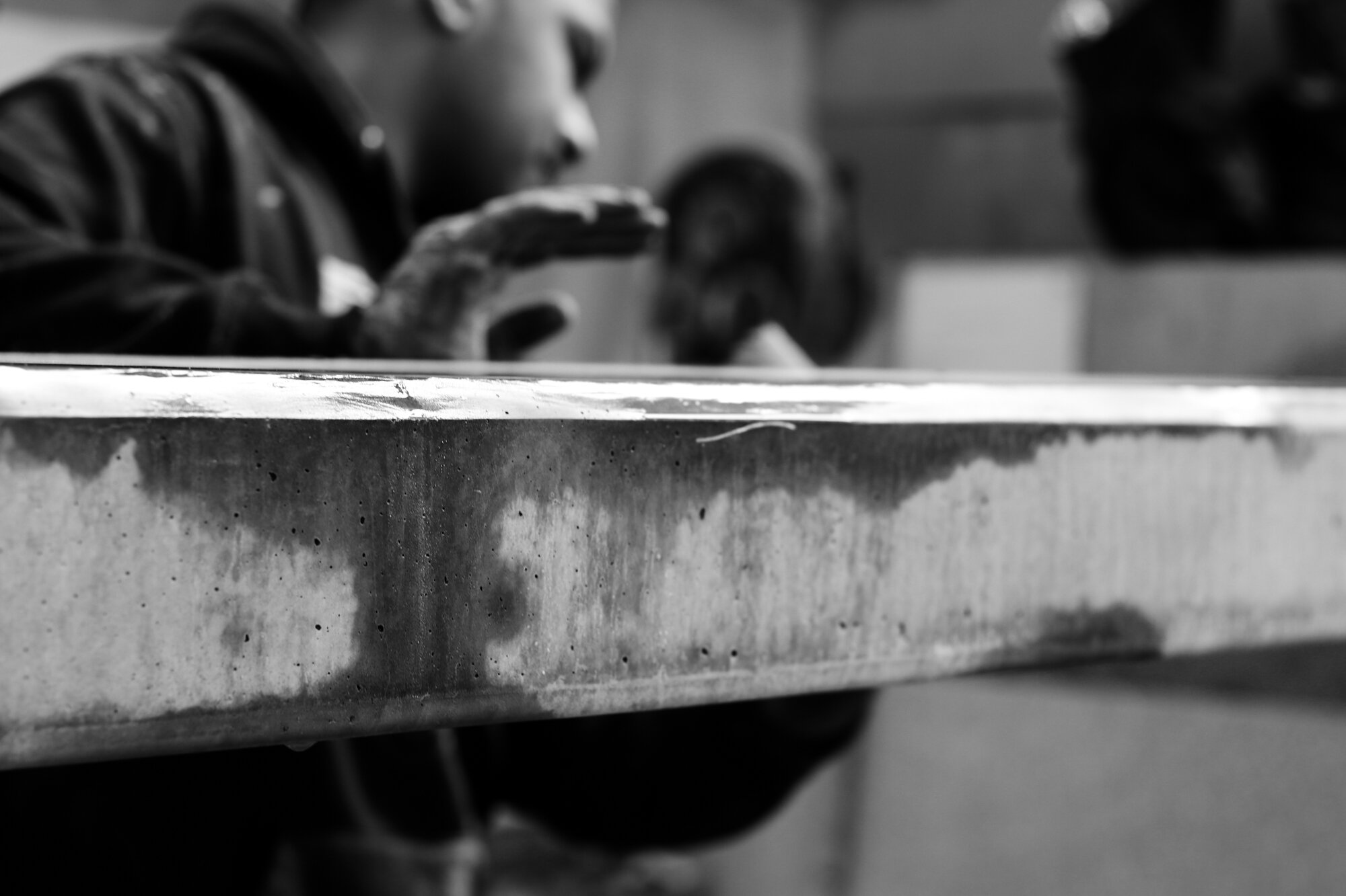
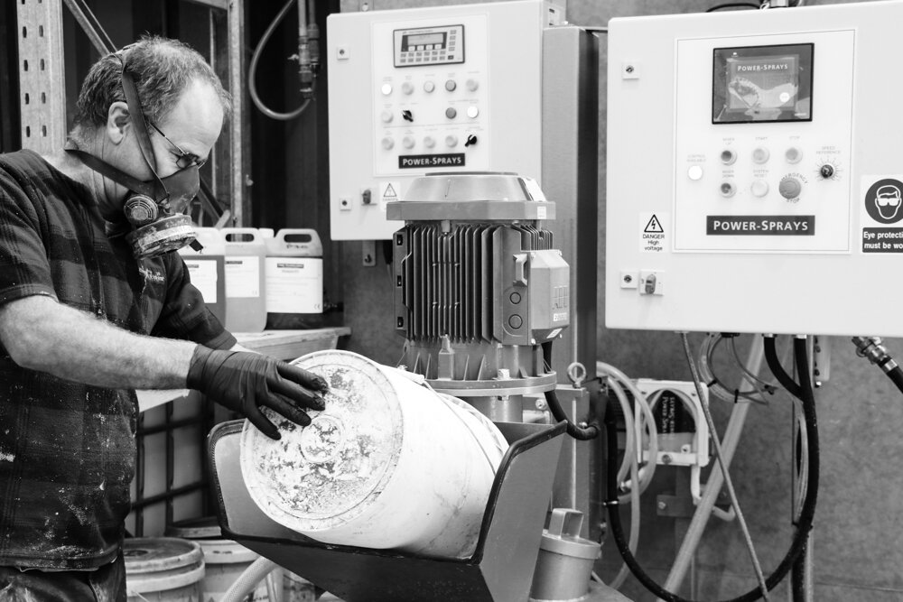
GRC is typically made in one of two methods, either ‘spray-up’ or ‘premix’. The method selected is largely dependant on the product being made (e.g. large flat panels vs complex 3D forms respectively) with each having their own advantages for the desired performance characteristics. With premix the fibre is pre-cut, mixed with the other ingredients and then hand pressed or trowelled into a mould. With the continuous spray method a glass fibre ‘roving’ is fed into a compressed air spray gun, where the fibres are cut to length and mixed simultaneously with a sand/cement slurry. Both methods require careful hand compaction into the mould using a spring roller.
For both methods Liquidstone first lay down a fine ‘mist’ coat which has no fibre onto the mould and this forms the decorative or face layer. Using this technique achieves a superior quality finish and often times means no additional post-production is required e.g. repairs, fairing, filling, painting etc.
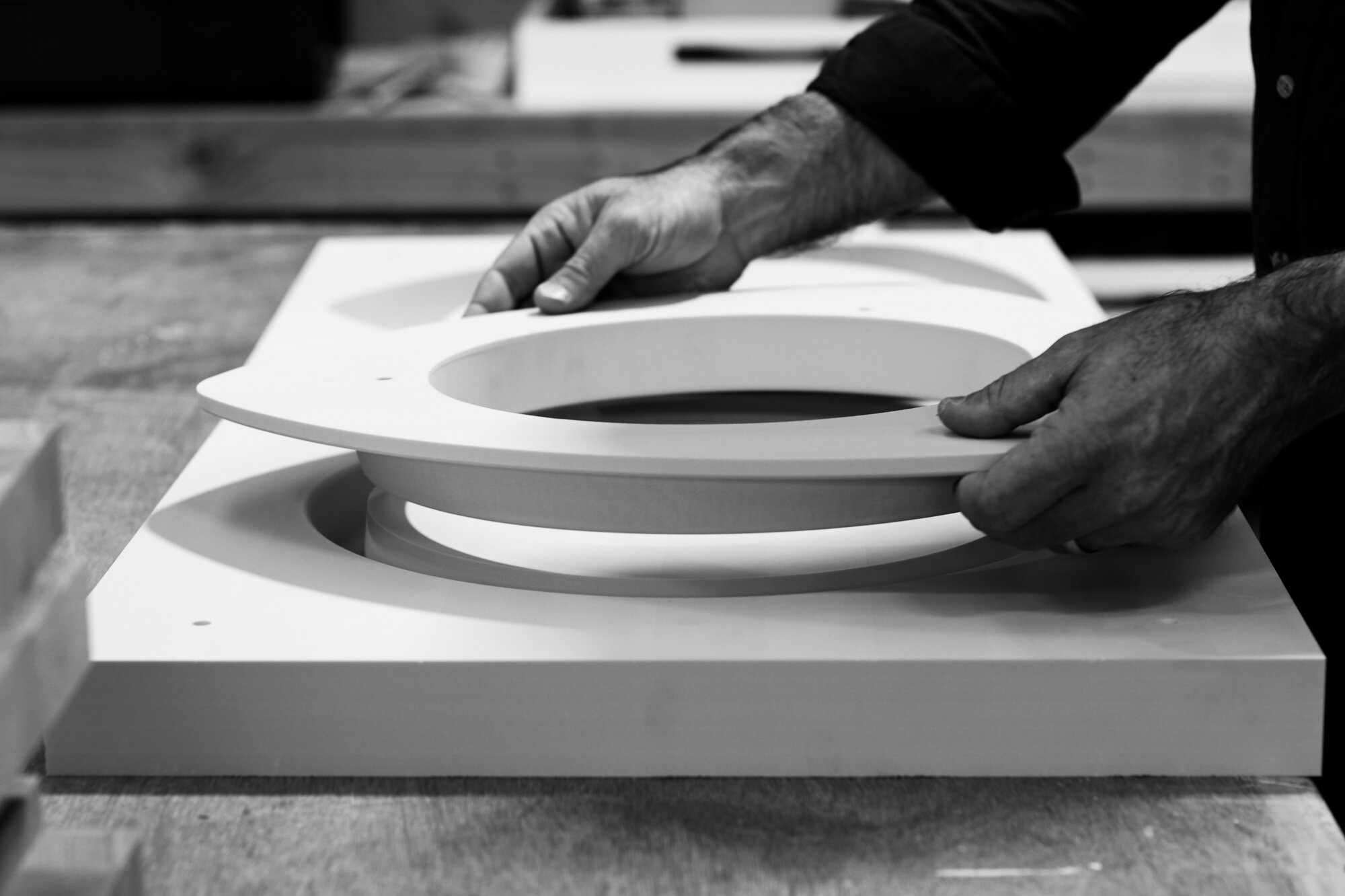
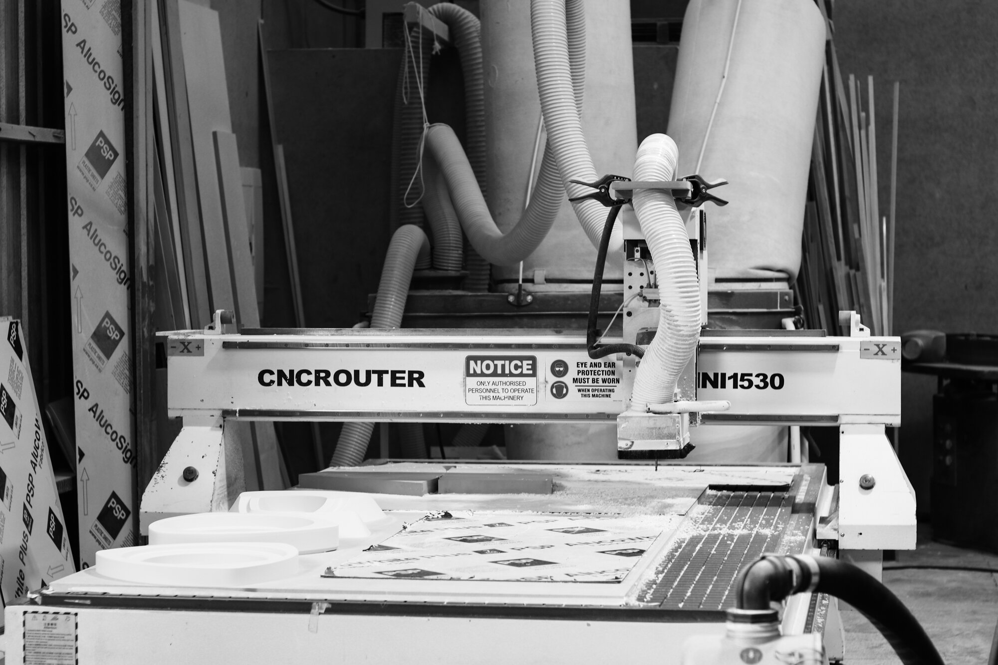
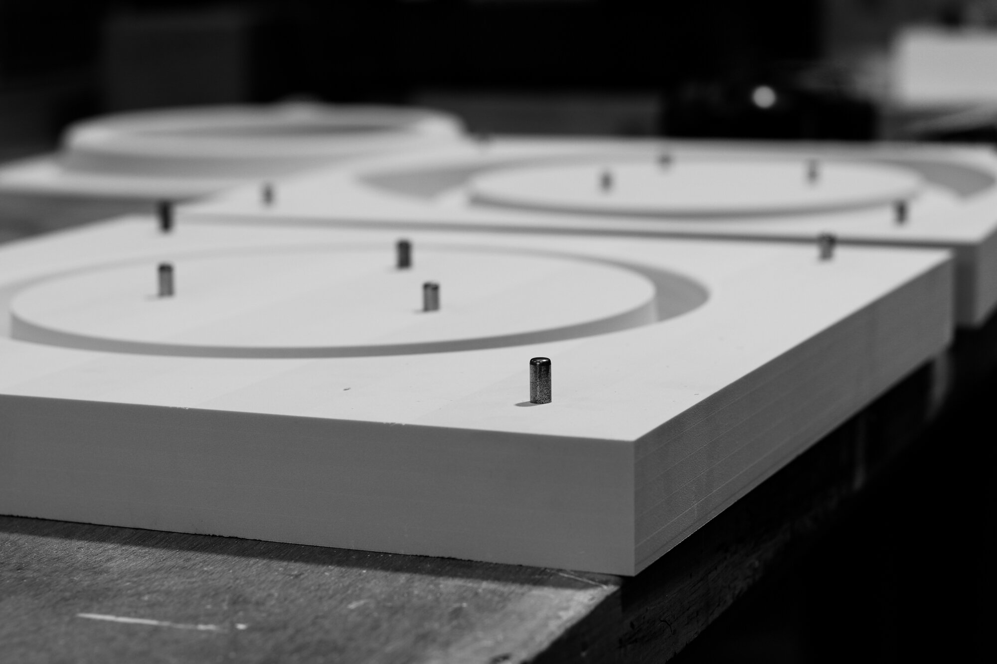
Moulds and formwork
Moulds can typically be made from a variety of materials such as MDF, Plywood, Steel, Fibreglass and Polyurethane rubber etc or a combination of one or all of these materials.
Careful consideration must be taken to select the most appropriate material or combination of materials for each mould or application e.g. a single use one-off product will likely have a mould made using low cost material such as MDF whereas a mass produced product may benefit from a more expensive mould made from fibreglass with a PUR rubber liner that can be used many 100’s of times.
Surface finishes and treatments
There are almost limitless possibilities for colour and texture that can be applied post-production
Off-form - smooth or textured surfaces, intricate patterns
Exposed / fine aggregate including ‘Graphic concrete’ and Sand-blasting
Mechanical abrasion - honing / polishing
Painting / Staining - a wide range of colours and effects are achievable
Hydrophobic coating and sealers

Why choose GRC?
DESIGN
Ability to reproduce fine surface detail and quality of finish
Easy to mould into complex shapes
Almost limitless possibilities for surface finish and colour
COST
Reduced product weight (24kg/m2 at typical 12mm thickness).
Reduced transport and installation costs
Less time on site
MAINTENANCE
Maintenance free (no steel to corrode)
Excellent fire properties
PERFORMANCE
Reduced loading on buildings and foundations
Excellent edge and corner strength
Excellent freeze/thaw resistance
Not affected by UV
Sustainability
Neither uses nor emits volatiles
low embedded carbon, low energy


Stud frame construction
Stud Frame Construction
A GRC stud frame cladding panel consists of a single skin of GRC attached to a prefabricated frame, usually metal, by means of L shaped flexible anchors (termed flex anchors) and support anchors (known as gravity anchors). Regular spacing of the flex anchors ensures that the effects of wind loading are evenly distributed over large areas of the panels. The flex anchors are for lateral support to the GRC facing whilst allowing some degree of rotation and shrinkage/moisture movement of the GRC. The gravity anchors are positioned along the bottom of the panels and support the self weight of the GRC. This form of construction has gained popularity particularly when very large and generally flat panels are to be made. The stud frame system allows panels of 10-20m2 to be manufactured, transported and erected.
Consideration needs to be paid to the material of the frame to avoid risk of corrosion and accordingly stainless steel or suitably treated and protected mild steel are used. This selection may depend on local building regulations. The wall construction is typically completed by an inner skin of gypsum plasterboard and the space between the outer and inner skins filled with insulating material such as rockwool to give thermal insulation and good fire resistance. Figure A: shows a typical arrangement of a stud frame for a rectangular GRC cladding panel.
Figures B to D: indicate how unbonded flex anchors and gravity anchors are intended to perform. Note how they all point to the centre of the panel to alleviate adverse shrinkage stresses.

Figure A: TYPICAL arrangement of Stud Frame
NOTE: All gravity and flex anchors point towards the centre of the panel to allow free shrinkage
The flex anchors allow vertical and horizontal shrinkage of the cladding panel. Vertical shrinkage is accommodated by rotation of the flex anchors, by virtue of using a hand tight, lock nut arrangement, whilst horizontal shrinkage is allowed by the debonding sleeve placed on the flex anchor before bonding it to the face. The self-weight of the panel is supported solely on the fixed gravity anchors which are also sleeved to allow horizontal shrinkage of the GRC towards the centre of the panel. Gravity anchors behave as a strut and tie system to support the weight of the panel (Figure D).
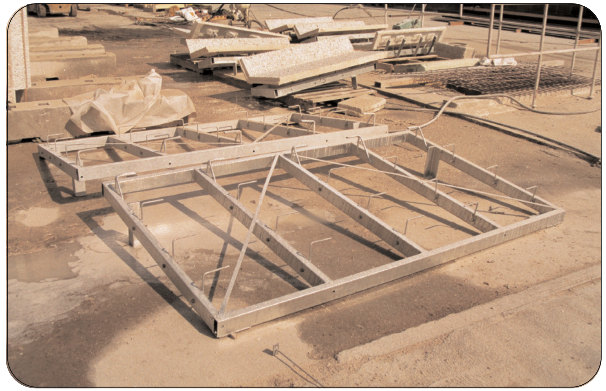
Figure B: Stud Frame fabricated from rectangular hollow Sections

Figure C: Typical Flex Anchor indicating degrees of freedom
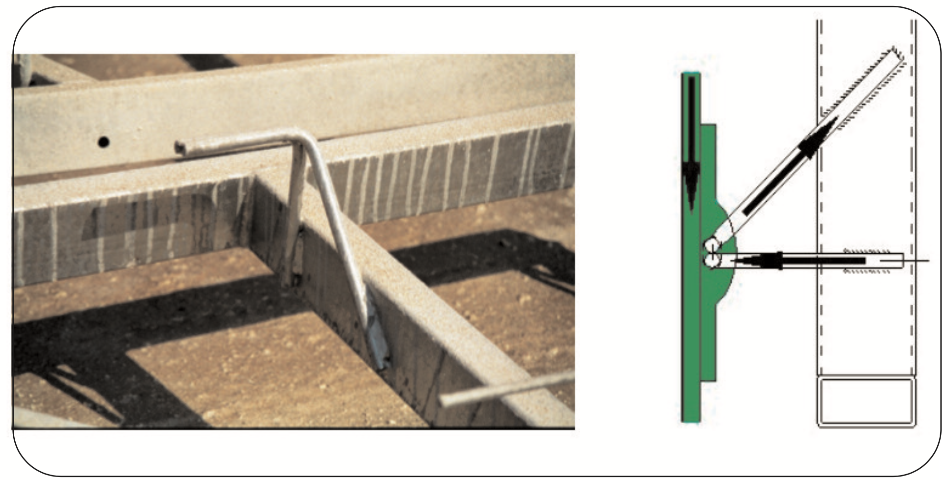
Figure D: Typical Gravity anchor acting as a strut and tie system
NOTE: All flex and gravity anchors should be fitted with debonding sleeves prior to constructing the bonding pads.